 跳到内容
跳到内容 

Got a great plastic part but no design files? Recreating it feels like an impossible task, risking costly errors and delays in your project.
Reverse engineering for plastic parts1 is the process of deconstructing a physical sample to create a digital 3D CAD model2. This model is then used to manufacture new, identical parts through processes like injection molding. It's about recreating a part without the original blueprints.
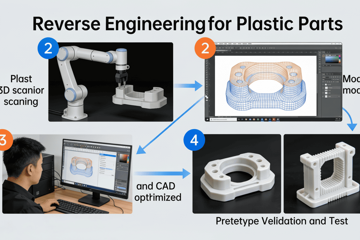
This might sound complex, but it's a systematic process we use regularly to help clients bring legacy parts or competitor products back to life. It's more than just copying; it's about understanding, refining, and recreating a design for manufacturing. Let's walk through how it actually works, step-by-step, from a physical sample to a mass-produced product.
How Do You Accurately Capture the Design from a Physical Part?
Trying to measure a complex part with calipers is inaccurate and slow. You worry that any small mistake will ruin the final mold and your entire budget.
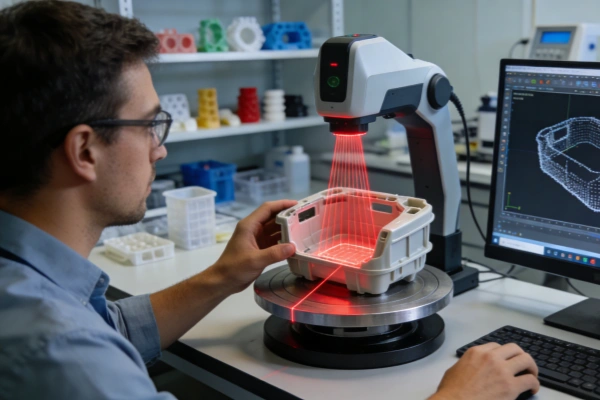
We capture the design using high-precision 3D scanners3. These devices measure millions of data points on the part's surface, creating a detailed digital "point cloud." This data is then used by our engineers to construct an accurate 3D CAD model, which is far more precise than manual measurement.
The first step is the most critical: turning a physical object into a perfect digital twin. This is where precision and expertise come together. I've had clients bring us worn-out components from decades-old machinery with no documentation. The success of the entire project hinges on getting this initial stage right. It's a process we call "抄数" (chāo shù), or data capturing.
From Physical to Digital: The Scanning Phase
We don't rely on guesswork. We use advanced 3D scanning technology to map every curve, hole, and feature of the sample part.
- 3D Scanning: A laser or structured-light scanner projects a pattern onto the part and measures its deformation from multiple angles. This captures the complete surface geometry as a dense collection of data points, known as a point cloud.
- Data Processing: This raw point cloud isn't a usable model yet. Our engineers then use specialized software to process this data, cleaning up any noise and converting it into a polygon mesh.
- CAD Modeling: The final step is the most skill-intensive. An engineer uses the mesh as a precise reference to build a "solid" 3D CAD model. This isn't an automated process; it requires an expert to interpret the design intent and create clean, manufacturable geometry. This final file (often a STEP or IGS file) is the digital blueprint for the new part.
This method ensures that the digital model is a faithful and highly accurate representation of the original sample.
How Can You Be Sure the New Part Will Fit Before Making an Expensive Mold?
You're about to spend thousands on a mold based on a digital file. What if it's wrong? The fear of a failed first run is keeping you up at night.
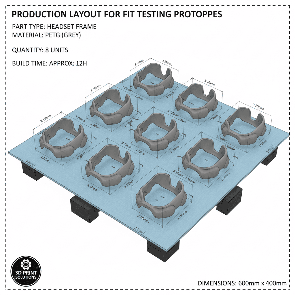
We eliminate this risk by 3D printing4 a physical prototype from the new CAD model. This allows you and your team to hold, test, and verify the part's dimensions and fit before any commitment is made to expensive tooling. It is a crucial validation step.
Investing in an injection mold is a significant financial commitment. The last thing anyone wants is to discover a design flaw after the steel has been cut. That's why we never proceed to tooling without a "test run" using rapid prototyping. It's an essential part of our quality assurance process5 that I insist on for all reverse engineering projects.
The Power of Prototyping
A 3D model on a screen can look perfect, but nothing beats a physical object you can hold in your hand.
- Prototype Creation: We take the newly created 3D CAD file and use our 3D printers to produce a physical prototype, often called a "手板" (shǒu bǎn). This can be done in a matter of hours or days, depending on the part's size and complexity.
- Verification and Testing: You receive this prototype. Now you can perform real-world checks. Does it fit with other components? Are the clearances correct? Does it feel right? You can test its function in your actual assembly.
- Iterative Refinement: If any issues are found—a dimension is off by a fraction of a millimeter, or a feature needs adjustment—it's not a disaster. We simply go back to the 3D CAD model, make the required optimizations, and print a new prototype. We repeat this cycle until you are 100% satisfied and give your final approval on the prototype.
This iterative loop de-risks the entire project. The cost of printing a few prototypes is tiny compared to the cost of modifying or remaking a steel mold.
How Does a Verified Design Become a Mass-Produced Part?
You have a perfect, client-approved prototype. Now what? You need to turn this one successful sample into thousands of identical parts without losing quality or precision.
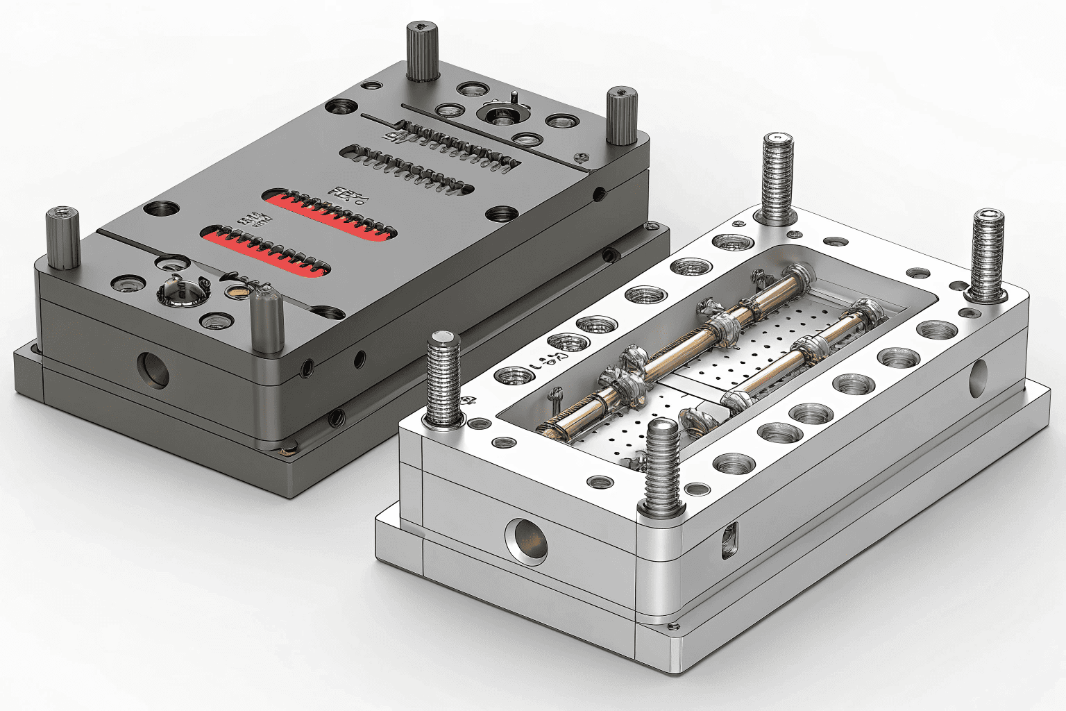
Once you confirm the final prototype is perfect, we use the corresponding 3D CAD model as the master blueprint. Our team then designs and manufactures the injection mold based on this exact file, ensuring the final mass-produced parts will be identical to the prototype you approved.
With your final sign-off on the prototype, the project moves from the design phase to the manufacturing phase. This is where our 15 years of experience in mold making and injection molding6 really comes into play. The approved CAD model becomes the single source of truth for all subsequent steps.
From Blueprint to Production
The transition to mass production7 follows a rigorous and proven workflow to guarantee quality and consistency.
| Stage | Action | Purpose |
|---|---|---|
| 1. Mold Design | Our engineers design the injection mold around your approved 3D part model. | This includes planning the gates, runners, cooling channels, and ejection system for optimal production. |
| 2. Mold Manufacturing | We use CNC machines8, EDM, and other precision equipment to create the steel mold. | The accuracy of the mold directly determines the accuracy of the final parts. We work to tolerances as tight as ±0.02mm. |
| 3. T1 Sample Production | The new mold is put into an injection molding machine to produce the first samples (T1 samples). | This is the first test of the production tool to ensure it functions correctly and produces parts to spec. |
| 4. Sample Confirmation | We send you these first production-grade samples for final approval. | You confirm that the parts produced from the final tool meet all your quality and functional requirements. |
| 5. Mass Production | Once you approve the T1 samples, we launch full-scale injection molding production. | We can now efficiently produce thousands or millions of parts, each one matching the quality of the sample you signed off on. |
This structured process ensures there are no surprises. What you approve as a prototype is exactly what you get in your mass production run.
Conclusion
Reverse engineering is a powerful, systematic process that turns a physical part into a mass-produced reality. It combines digital scanning9, rapid prototyping, and expert mold making to de-risk development.
Explore this resource to understand the intricacies of reverse engineering and its applications in plastic manufacturing. ↩
Learn about the process of creating a 3D CAD model, which is crucial for accurate manufacturing. ↩
Find out how high-precision 3D scanners capture detailed measurements for accurate modeling. ↩
Discover how 3D printing is used to create prototypes for testing and validation. ↩
Understand the quality assurance measures that ensure product reliability and performance. ↩
Discover the injection molding process, a key method for producing plastic parts efficiently. ↩
Understand the mass production process and how it ensures consistency and quality. ↩
Discover the role of CNC machines in creating precise molds for production. ↩
Learn about digital scanning techniques and their application in reverse engineering. ↩

